Resolving USB Conflicts with Virtual COM Ports

Print Friendly, PDF & Email

If you run multiple USB devices that operate as virtual RS232 COM ports (the ubiquitous serial port standard) on Windows, you may have run into problems with conflicts between devices. An application may connect to the appropriate device when it’s the only one connected, only to “get confused” if there is another device sharing the PC. Happily, there are a few simple things you can try that will often resolve the problem.

9103s and Arduinos Playing Nice Together

9103 and Arduino USB Devices

A 9103 Picoammeter and Arduino

To most Windows applications, virtual COM ports (VCPs) all look the same. An application can open a port and and attempt to communicate with the connected device, but since there’s no fixed protocol – each device speaks its own “language”, any message sent can have undetermined effects if the device you’re communicating with is not the one your were expecting. Some applications simply connect to the first COM port available, other’s may provide a way to select the COM port your device is connected to – but you’re still responsible for figuring that out.

When manufacturers produce hardware for PCs they can apply for unique vendor ad product IDs for their device, and there are ways for applications to safely query these. But that only solves part of the problem. Many devices use third-party USB chips and drivers from companies like FTDI, so they share the same IDs. These devices look the same to a Windows client application, or to a person perusing the Device Manager in Control Panel.

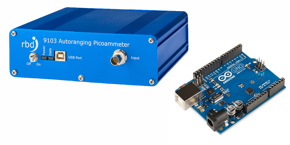
RBD’s own 9103 Picoammeter utilizes FTDI’s popular USB VCP chips, as do many versions of the popular Arduino microcontroller boards, so these two sets of devices can be confused by client applications when used on the same PC. And s it turns out, they are often used together. Here are a few tricks for getting these device to play nice together.

Solution 1: Connect Each Device and Run Each Client in Order

Many applications require you to specify the port for the selected device. Others (like Actuel for the 9103) poll the COM ports in numerical order and check and connect to the first available. If these devices first check the vendor and product ID (like the 9103), they will at least skip ports that do not match. But they cannot distinguish between two devices using the same USB chip (like FTDI’s). Setting up a device connection / application order can solve this.

In the case of a 9103 / Arduino conflict, remove all other devices, then plug in the 9103 and power it on. Next run the Actuel software. The software will find and take control of the 9103 port, and once assigned, you can safely plug in the next device and run its client.

Another order might make more sense for your particular application. Experiment with your configuration, and there are more than two devices, try getting two working first. Document the process and just make sure it’s followed anytime you reboot / power-on.

Solution 2: Change the COM Port Number for a Particular USB Port

You can force Windows to use a different COM port number than the one automatically assigned. This may help with applications that select the lowest numbered port.

For example, if the 9103 is connected to COM4 and another FTDI device is on COM3, the 9103 client software may incorrectly select the device on COM3. Setting the 9103 to COM2 may allow you to now connect the devices and run the client applications in any order, depending on how those other devices / applications behave. Some experimentation may be necessary.

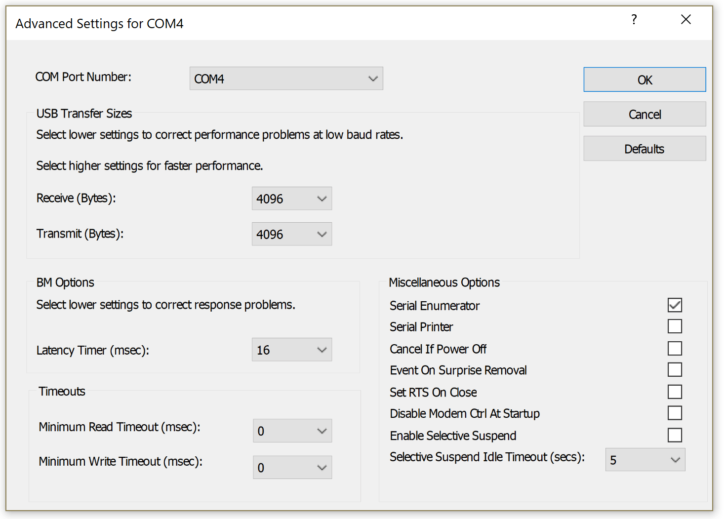
With the 9103 connected and turned on, run Control Panel / Device Manager, and find the selection for “Ports (COM and LPT)”, click and you should see an entry for “USB Serial Port (COM4)” (the COM# may be different of course). Double-click for properties.

The COM port settings for the 9103 USB VCP

The COM port settings for the 9103

Now select the “Port Settings” tab, and click the “Advanced…” button. From this window you can select a new COM port assignment:

Choosing a COM port for the 9103

Choosing a COM port for the 9103

Keep in mind that plugging a device into different USB port will change the COM port assigned to it.

More Info

Of course, you’ll want to ensure you have the latest drivers installed. For FTDI, they can be found here:

http://www.ftdichip.com/FTDrivers.htm

If you’re thinking of programming your own serial port application, here’s a quick tutorial at the API level. Many popular languages include code for VCP programming, and third-party libraries are available:

http://xanthium.in/Serial-Port-Programming-using-Win32-API

Loading PHI specimen mounts

Print Friendly, PDF & Email

Loading PHI specimen mounts

This post explains the mechanics involved with loading PHI specimen mounts used on most of the older to current Physical Electronics surface analysis systems.

There are a number of different sizes and shapes of specimen (sample) mounts and they all use the same basic mounting and docking scheme.

The most common sample mount used on older Physical Electronics XPS and AES surface analysis systems is the Model 190 flat one inch diameter specimen holder shown below.

Model 190 sample mount

Model 190 sample mount

The basic concept is that there are two grooves on the outside of the sample mounts which are used to transfer the sample mount into the vacuum chamber, and to dock the sample mount to the specimen stage. The transfer arm has a fork on the end which connects to the bottom groove on the specimen mount and the specimen stage has three clips which snap into the bottom groove and hold the specimen mount to the stage.   The top groove is used to hold the specimen mount while mounting it to the transfer arm fork or in the case of scanning auger systems, to transfer to the parking attachment.

one_inch_sample_mount_from_side

Grooves on 190 specimen mount

Clips on specimen stage

Clips on specimen stage

There are two essential steps required to successfully dock and removing the specimen holders;

  1. Make sure that the specimen stage is perfectly centered under the transfer arm fork.
  2. The specimen stage center clip needs to be lined up with the notch on the transfer arm fork.
Line up intro fork notch to clip

Line up intro fork notch to clip

line up sample over specimen stage

line up sample over specimen stage

Once you have the location of the specimen stage micrometers for the load and un-load positions you can make some marks on the specimen stage micrometers so that you will be able to easily re-position the specimen stage for loading and unloading.

 Loading PHI sample mounts procedure:

  1. After you attach the sample that you want to analyze to the specimen holder (using screws and clips or carbon/silver tape). Back-fill the intro with dry nitrogen and mount the specimen holder to the sample fork. There are 2 different types of specimen mount holding tools as shown below. Or you can use a clean needle nose pliers. Pull the transfer arm out a little bit so that you can lower the specimen mount into the load lock and then move the transfer arm back in so that the fork slides over the bottom groove on the specimen mount.
    specimen mount  holding tool

    specimen mount holding tool

    sample holding tool

    sample holding tool

  2. Pump down the load lock by pressing the Pump Intro button on the AVC remote box.
  3. Move the specimen stage micrometers to the load sample position. The X and Y axis will be centered under the intro fork but the Z axis will be lowered from the dock position by at least 1 cm.
  4. After the load lock has pumped down (5 bars on the AVC remote plus a few more minutes – the longer you pump the sample, the lower the pressure burst and the less out-gassing you will have) press the  Intro Sample button on the AVC remote and the V1 gate valve will open.
  5. Move the intro arm forward to bring the sample into the vacuum chamber and push it all the way in until it hits the stop. If adjusted properly, the stop will be the correct position for docking the specimen mount.
  6. The specimen mount should be directly above the specimen stage clips.  If not adjust the X and Y on the specimen stage as needed.

    one_inch_sample_puck_above_specimen_stage

    one_inch_sample_puck_above_specimen_stage

  7. Raise the specimen stage Z axis so that the clips slide into the specimen holder bottom groove. You may need to slightly adjust the X Y or rotation (if so equipped) so that the specimen holder snaps into the clips.   Slightly moving the specimen stage rotation or the tilt on the transfer arm can also help the specimen mount to snap down into the clips on the specimen stage as you move the specimen stage Z axis.   If the specimen mount does not snap down with a minimal amount of force, back off and recheck the specimen stage X and Y position.  You do not want to damage any of the three clips on the specimen stage by crushing them. Once the clips have snapped in adjust the Z slightly until there is no gap between the bottom of the specimen holder and the specimen stage.

    one_inch_sample_puck_docking

    one_inch_sample_puck_docking

  8. After the specimen mount is docked to the specimen stage, slowly retract the intro fork until it separates from the specimen holder and then once clear, pull the intro arm all the way out of the chamber. The V1 gate valve will close automatically.

To remove a sample from the system, repeat the above procedure with the exception that the Z axis should be in the dock position so that the intro arm fork mounts to the lower groove of the specimen mount. Once you dock the load lock fork to the specimen mount, drop the Z axis on the specimen stage in order to separate the specimen holder from the specimen stage clips.

When the specimen holder is clear of the specimen stage you can pull the intro arm all the way out of the chamber and V1 will close automatically.

RBD Instruments provides new and used PHI specimen mounts.  We also provide the sample clip assembly. Contact us for more information.

RBD specimen mount part numbers

RBD specimen mount part numbers

This slideshow requires JavaScript.

X-ray source arcing

Print Friendly, PDF & Email

X-ray source arcing results in unstable XPS data and can also damage the x-ray source power supply or high voltage control.

Typically X-ray source arcing is caused by contamination on the anode, a coated anode support ceramic (the football ceramic) or a loose filament.

However one unseen cause of x-ray source arcing is when the high voltage cable to the x-ray source is not tightened all the way down until it snaps in. The procedure is simple – line up the slot on the cable with the two little tabs on the source connector. Then press down all the way and turn the cable collar clockwise until it snaps in.

On the newer 04-548 15kV dual anode sources this is easy to do as the connector is exposed. But the connector is recessed on the older dual anode sources and all of the mono sources.

To properly connect the high voltage cable on the older dual X-ray sources or a mono source you need to remove the cover on the source so that you can see the connector and make sure that the cable slots line up and that the cable locks down when the collar is turned fully clockwise.

high-voltage-connector-slots

high-voltage-connector-slots

high-voltage-connector-snapped-in

high-voltage-connector-snapped-in

If the high voltage cable is not snapped all the way down then it can arc at higher voltages and damage the cable connector, the source connector, or more typically both connectors.

The pictures below show damaged cable and source high voltage connectors.

melted x-ray source connector

melted x-ray source connector


burnt x-ray source connector

burnt x-ray source connector


Once arcing damage occurs the cable end and or source connector need to be replaced.

RBD Instruments provides the source connector and we can also repair or exchange your cable. Visit our website and look under Parts – Optics – X-ray Photoelectron Spectroscopy Model 04-500 and04-548 X-ray source parts or call us at 541 550 5016

Revised outgas procedure for PHI dual anode x-ray sources and single anode mono sources.

Out-gassing the filaments and conditioning the anode are essential steps needed to remove adsorbed gases from the filament area of any PHI X-ray source.

Recently I have seen a couple of instances where a 10-610 monochromator source was not properly out-gassed and the result was a contaminated anode and very low counts. So degassing the anode is essential for proper operation.

To prevent anode contamination, the anode needs to be degassed per the PHI manual. However I have found that by changing the order of the out-gas procedure steps that the amount of time it takes to out gas the source to full power can be significantly reduced.

The manual states that the out-gas procedure sequence is as follows:

  1. Outgas the filaments
  2. Condition the high voltage
  3. Degas the anode

But from a practical standpoint it makes more sense to degas the anode before conditioning the high voltage. The reason is that a degassed anode is less likely to arc.

So the faster way to out-gas an X-ray source is:

  1. Outgas the filaments
  2. Degas the anode
  3. Condition the high voltage


Step 1. Outgas the filaments.

You need to out-gas the filaments after new filaments have been installed or anytime the system has been brought up to air and baked out. For this procedure it is assumed that the system has been baked out. (The only bake out exception is if you have just replaced the 04-303 ion gun ionizer and back-filled the chamber with dry nitrogen).

  1. Turn on the 32-095/096 power.
  2. On the 32-095/6, press the Blue Out/Act out-gas activate button.
  3. Select both filaments
  4. Select the Mg filament (or filament 1)
  5. Slowly increase the amps to 3.5
  6. Select the Al filament (or filament 2)
  7. Slowly increase the amps to 3.5
  8. Let the filaments sit there for a few minutes and then slowly increase each filament to 4.5 amps.
  9. Let the filaments sit at 4.5 amps for a minimum of 4 hours (overnight is best).
  10. After out-gassing for at least 4 hours set the filament current to zero on both filaments and turn off the Out/Act out-gas button by pressing it one more time.

Step 2 Degas the Anode

  1. Set the beam voltage to 500V and turn it on.
  2. On the 32-095/6, press the Blue Out/Act out-gas activate button
  3. Select the Mg filament (or filament 1)
  4. Slowly increase the amps to 3.5 and then monitor the anode current (emission current) meter.
  5. VERY SLOWLY increase the filament current until you get 1mA of emission current. Do not exceed 5 amps of filament current. Do not exceed 2mA of emission current.
  6. Monitor the ion gauge vacuum reading and wait until the out-gassing comes back down then slowly increase the beam voltage to 1 kV. If necessary reduce the filament current to keep the emission below 2mA.
  7. In steps of 1kV bring the high voltage up to 10kV while adjusting the filament current as needed to keep the emission current below 2mA. Do this over a period of 10 minutes to several hours, depending on how much the anode out-gasses. For best results keep the vacuum in the chamber in the low 10-9 Torr range. The higher the pressure from out-gassing, the more likely an arc will occur.
  8. Once the anode has been out-gassed to 10kV, turn the filament current to zero and set the high voltage to zero. Then switch to the other filament and repeat the procedure.

Step 3 Condition the high voltage

  1. Make sure that the Out/Act button is OFF and that the filament current is set to zero on both filaments.
  2. SLOWLY bring the high voltage up to 10kV while monitoring the vacuum chamber ion gauge.
  3. Step the high voltage up increments of 500V until you get to 16.5kV. When you see some signs of out-gassing (the pressure in the vacuum chamber will come up) then back down the high voltage a little bit and wait until the vacuum recovers.
  4. Once you are able to get to 16.5 kV with no arcing, let the anode sit there for at least 20 minutes.

The X-ray source is now ready for normal operation.   For best results, start at a low power and kV such as 100 watts and 10kV.   You can step up both the power and the kV over a period of a few hours based on how much out-gassing you see when operating in this mode. Once you are up to full power of 300 watts and 15kv the X-ray source can be brought up to full power quickly.