A blog on the repair, operation and calibration of surface analysis systems and components including electron spectrometers, sputter ion guns and vacuum related hardware. Click on the Index tab below to see a list of all posts. Visit our website at http://www.rbdinstruments.com
Lanthanum hexaboride (LaB6 ) filaments provide a very stable emission of electron current in the hot cathode electron sources used in many scanning Auger electron spectrometers. However, this type of filament is susceptible to deactivation from vacuum contaminants such as fluorine.
If your LaB6 filament becomes contaminated it may exhibit symptoms such as unstable emission current or no emission current at all. The Auger data below shows instability in the background that was caused by unstable emission current from the cathode.
Usually it is possible to rejuvenate a LaB6 filament by backfilling the chamber with Oxygen while monitoring the emission current as outlined in the procedure below.
LaB6 filament: rejuvenation procedure:
Set the beam voltage to 1kV and the emission voltage to 100% (or the maximum for that beam voltage).
Increase the filament current up to the normal operating value. 1.3 to 1.5 amps is typical for a PHI 600 or 660 scanning auger spectrometer.
Bleed O2 into the system to about 5 X 10 -7 Torr.
Slowly reduce the emission voltage until you get about 50uA of emission current. Keep an eye on it, as the O2 cleans the filament the emission will rise and you will need to increase the emission voltage in order to keep the emission current from going up too much. The maximum recommended emission current is 100uA.
Once the emission current is stable then you can turn off the O2. This process typically takes 5 to 20 minutes. In some cases the vacuum chamber may have some low level contamination where the emission current of the filament will drop once the O2 is turned off. In those cases, you may want to leave the O2 on for an extended period of time at a higher vacuum such as 2 X10⁻⁸ Torr.
If rejuvenating the filament does not work then the filament may need to be replaced. RBD Instruments Inc. provides LaB6 filaments for the Physical Electronics PHI 590 through 660 series scanning auger spectrometers. Visit us at rbdinstruments dot com
For the purpose of checking the performance of a surface analysis spectrometer such as a cylindrical mirror analyzer (CMA) or spherical capacitive analyzer (SCA), looking at an ion induced low energy electron peak can be extremely helpful. The peak typically occurs at about 20 to 50 eV and the size if the peak is directly related to both the alignment of the ion beam to the analyzer as well as the amount of ion current.
Checking XPS Performance
Set up an alignment for a range of zero to 100 eV kinetic. The eV range in binding energy depends on which anode energy you have selected in the software. See the table below. Most systems use an Al anode, so the energy would be 1480 to 1380 eV (which is about 0 to 100 eV kinetic).
Using a blank sample mount, position a sample to the focal point of the analyzer.
Look under the Hardware Properties Menu for XPS and note the X-ray Anode type.
Set up an alignment with the following parameters:
Upper Limit 1480 eV if Al is the anode, 1250 eV if Mg is the anode.
Lower limit 1380 eV if Al is the anode, 1150 eV if Mg is the anode
EV per step .5 (or the closest selection .5)
Time per step 20 ms
Start the alignment and turn on the ion gun (no raster). You should have a low energy peak at around 20 to 50 eV kinetic.
If necessary, reduce the ion gun beam current to prevent the detector from saturating. (You can increase the ion gun condenser lens setting or reduce the emission current in order to reduce the ion beam current).
If you do not get the peak, then you have a problem with the analyzer or analyzer electronics. If you do, then the analyzer and electronics are probably OK.
This is a very useful technique for isolating a low signal XPS problem between the analyzer and the X-ray source. You can also use the low energy peak to rough in the alignment of the ion gun to the XPS analyzer focal point.
Checking AES Noise Level
Analyzer noise (noisy data) can be caused by these things:
Poor contact between the inner and outer cylinder terminating ceramics
Analyzer control
Electron Multiplier supply
Electron gun control or Electron gun high voltage supply
This technique will help isolate analyzer noise by determining if it is related to the electron gun, which in tern would be caused by the electron gun control or electron gun high voltage supply.
Overview
This procedure uses both the electron gun and ion gun as a source to generate low energy electrons. By comparing the relative noise levels, you can determine if the problem is related to the electron beam only, or both beams. If it is related only to the electron beam, then the problem is in the electron gun control or electron gun high voltage supply.
If both the electron and ion beams are noisy, then the problem is either the analyzer control, multiplier supply or poor contact in the analyzer. The analyzer control and electron multiplier supplies can be tested for noise using the appropriate calibration procedure.
Procedure
This procedure was written specifically for a Physical Electronics 600 scanning auger system, but the principles can be applied to other systems as well.
Set up an alignment with these parameters:
Lower Limit 0, Upper Limit 100, EV per step 1, Time per step 20 ms
In AugerScan, go to the Multiplier Properties dialog box and uncheck the Auto EMS box. This will keep the computer from trying to automatically set up the electron multiplier voltage.
In AugerScan, go to the Hardware Properties dialog box and make sure the input is VF1.
With the electron beam on and set up for a normal elastic peak, start the acquisition and manually adjust the 32-100 CMA electron multiplier until you have a maximum count rate of approximately 100Kcps. You will see a low energy peak around 20 to 50 eV depending on your sample.
Use the yellow cycle stop button to end the alignment and then save the file.
Blank the electron beam and turn on the ion gun. Do not use any raster.
Start the acquisition and manually adjust the 32-100 CMA electron multiplier until you have a maximum count rate of approximately 100Kcps.
Use the yellow cycle stop button to end the alignment and then save the file.
Compare the two files to determine whether or not they have similar amounts of noise. In the examples shown below, then electron gun as a source exhibits more noise than the ion gun as a source. In this instance the problem was isolated to a noisy emission supply in the 20-610 High Voltage supply on a 600 system.
Ion Gun Alignment
On systems that do not have scanning electronic guns for TV imaging, you can use the low energy peak to center the ion beam with respect to the analyzer focal point. If you have scanning then you can simply look at the ion beam in real time on a SiO2 sample.
AES Ion Gun Alignment Procedure (for non-scanning AES):
Using a blank sample mount, position a sample to the focal point of the analyzer (Elastic peak).
Set up an alignment with the following parameters:
Lower limit 0 eV
Upper Limit 100 eV
Time per step 20 ms
In the Multiplier Properties dialog box, un-check the Auto EMS Box.
In the Hardware Properties dialog box, make sure the input is V/F1.
On the 32-100, set the CMA multiplier switch to Analog and make sure the potentiometer is fully CCW.
Start the alignment and turn on the ion gun (no raster).
Slowly turn up the 32-100 CMA multiplier supply (or the 20-075 multiplier supply if you have an older system) until you have about a 100K cps low energy electron peak at 20 to 50eV. This should occur at no more than 2000 volts on the multiplier (5.0 on the 32-100 potentiometer).
Finally, adjust the X and Y position of the ion gun for maximum signal. The ion gun is now aligned to the focal point of the analyzer.
XPS Ion Gun Alignment Procedure:
Using a blank sample mount, position a sample to the focal point of the analyzer.
Look under the Hardware Properties Menu for XPS and note the X-ray Anode type.
Set up an alignment with the following parameters:
Upper Limit 1480 eV if Al is the anode, 1250 eV if Mg is the anode.
Lower limit 1380 eV if Al is the anode, 1150 eV if Mg is the anode
EV per step .5 (or the closest selection to .5)
Time per step 20 ms
Pass Energy 100 (or the closest selection to 100)
Start the alignment and turn on the ion gun (no raster). You should have a low energy electron peak at around 20 to 50 eV kinetic.
If necessary, reduce the ion gun beam current to prevent the detector from saturating. (You can increase the condenser lens setting or reduce the emission current in order to reduce the ion beam current).
Finally, adjust the X and Y position of the ion gun for maximum signal. The ion gun is now aligned to the focal point of the analyzer. Once roughed in you can use a piece of TaO5 to check the alignment of the ion gun with respect to the system microscope because when you burn through the oxide layer you will see a blue ring on the TaO5 sample. RBD Instruments provides TaO5 samples for this purpose.
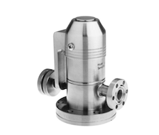
This post is about how to adjust the 951-5100 and 951-5106 Varian variable leak valve commonly found on vacuum chambers across the globe. Invented in 1968 by William Wheeler and Paul Hait, the patent was assigned to Varian Associates; many thousands of these valves have been built since then. In 2010, Varian was purchased by Agilent Technologies and since that time it has been harder to find the rebuilt kits for these variable leak valves. The order information for the rebuild kit can be found at the bottom of this post, as well as a link to the instruction manual.
Varian variable leak valve
Overview-
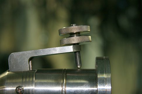
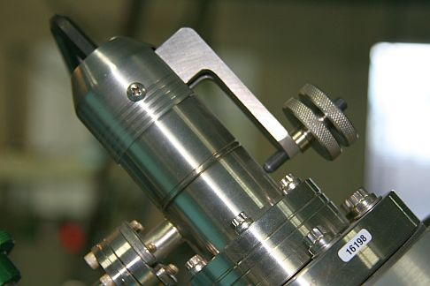
When this type of variable leak valve does not close all the way, operators will usually unlock the two knurled knobs and move them up the fine drive screw assembly and then re-lock them. What that does is to allow the handle to move out further from the valve body and put more pressure on the sapphire, which effectively closes the valve. That works fine for periodic adjustments to close the valve. However, if the handle is far away from the valve body it is possible to get too much leverage and crack the sapphire (which causes catastrophic valve failure) and also reduces the range of the valve arm. The picture below shows a valve handle that is too far away from the valve body and needs to be reset.
Adjustment procedure –
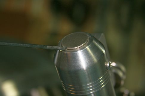
When properly adjusted, the handle will be parallel to the valve body when closed. Gas should just start to leak into the vacuum chamber when the knob is turned CCW by 2 full turns. The following procedure is an abbreviated version that I use which works most of the time. For a more thorough explanation of this adjustment refer to the manual.
CAUTION! Read and understand the procedure and notes before you attempt the adjustment on your system. You need to know exactly how much gas pressure you are putting into the valve, how much you need to adjust the valve by and the status of your vacuum chamber. The roughing screw is very sensitive; a very small amount of adjustment can be the difference between success and a dumped system!
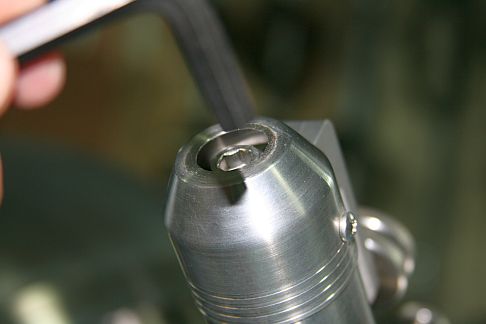
1. Use a small straight blade screwdriver to remove the hole cover on the back end of the leak valve to expose the roughing screw cap hex head.
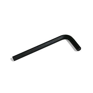
2. Insert a 5/16” Allen wrench into the cap head of the roughing screw
3. Monitor the vacuum in the chamber. For most PHI surface analysis systems the vacuum should be in the low 10-9 Torr or lower. 4. If necessary, adjust the handle so that it is parallel to the valve body. The knobs will need to be adjusted – turn the top knob CCW while holding the bottom knob in place. That will separate the two knobs and then you can spin them one at a time into position. Lock them on the fine drive screw assembly by holding the bottom knob in place and turning the top knob CW until it firmly butts up against the bottom knob. There is a spring washer between the two knobs that helps to lock them together. Once set, always turn both knobs together when opening (turn CCW) or closing (turn CW) the valve.
NOTE: Keep an eye on the vacuum in the chamber as you SLOWLY adjust the handle. If the pressure starts to increase, turn the Allen wrench CW by a few degrees to close the valve. The roughing screw is coarse threaded and so a very small movement on the Allen wrench has a large effect on the valve, whether closing (CW) or opening (CCW). The maximum torque that should be applied to the roughing screw is 6 foot lbs.
5. Once the handle has been set so that it is parallel to the valve body and the valve is closed (no gas leaking into the chamber) you are ready to adjust the open position of the valve. 6.SLOWLY turn the knob (both knobs turn together) CCW while observing the vacuum in the chamber. You want to get to two full turns without bleeding any gas into the chamber. If you start to see leakage before two full turns on the valve, compensate by turning the Allen wrench CW slightly until the leakage stops and the vacuum starts to recover. 7. Once you have the valve open two full turns with no leakage, SLOWLY turn the Allen wrench CCW in increment of 1 to 2 degrees at a time until the gas just starts to leak into the vacuum chamber. Then close the leak valve by turning the knob fully CW (two turns). 8. Verify that the gas just starts to leak into the vacuum chamber at about 2 turns. If necessary, adjust the Allen wrench in very small increments. Sometimes it is not possible to have the valve open at two turns. It may not open until as many as 6 turns, and that is still acceptable. The idea is to have predictable, smooth and repeatable control. 9. When you close the valve, go just finger tight – do not over tighten the knob or you will damage the threads on the fine drive screw! The fine drive screw should be periodically lubricated, I prefer C5A over moly-disulfide.
NOTE: If you are adjusting the leak valve after connecting a pressurized gas bottle for the first time, have the Allen wrench inserted into the roughing screw so that you can quickly close the valve further if the pressure in the chamber rises. Sometimes a valve will seal fine in atmosphere but leak when up to 500 PSI is applied to the back end of the valve. The valve is rated for a maximum of 500 PSI inlet gas pressure, but it will work better with 100 PSI or less.
If this procedure does not work, then the valve may need to be cleaned or the sapphire and gasket assemblies replaced. There is a limited lifetime on the gasket assembly as the copper gasket becomes compressed with each use. The manual specifies anywhere from 20 to 300 valve closures based on whether or not the valve is baked out or not. However, on the surface analysis systems where I have seen these valves used, they can operate for many years with little or no adjustment.
Refer to the manual for cleaning and rebuild instructions as well as a more detailed adjustment procedure.
To place an order, the following information is required: Purchase order number or credit card, delivery date, ship to, invoice to, end user, and quote number. GSA customers please provide GSA contract #.
2) Call 1-800-882-7426 (option 1) any weekday between 8 am and 7 pm Eastern time, in the U.S., and Canada. You will need to know the purchase order or credit card number the order was placed on.