9103 Picoammeter Actuel Update: Micro Window Display

Link

Print Friendly, PDF & Email

UPDATE: A new Actuel Beta featuring the micro window display is now available.

The Problem: Using Actuel to control and measure current with the 9103 Picoammeter takes up valuable screen real estate:

Actuel is RBD’s Windows application for controlling the 9103 USB Picoammeter. It also provides features like measuring, recording, and graphing current. Although the data recording and graphing display is a separate, optional window, the controller  and measurement window still take up quite a bit of screen real estate.  Sometimes, you just want to display the current unobtrusively while performing other work on your PC.

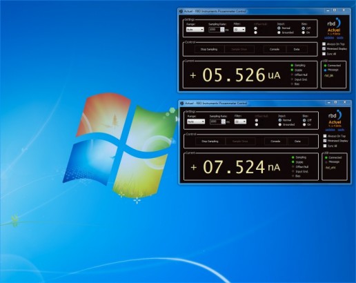
The Solution: A “Micro” version of the Actuel window that displays only the current and stability.

In response to customer requests, we’ve added a miniature display option to Actuel. By selecting an option in the main window, you can instruct Actuel to display a smaller window when minimized. This windows is much smaller than the main form, yet large enough to be viewed at some distance – a handy feature in many lab environments.

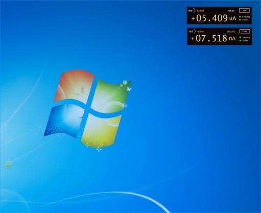
This “micro” window can be moved anywhere on screen and is always displayed on top of other windows. This allows you to use other applications (like RBD’s AugerScan) while simultaneously monitoring current without taking up precious screen real estate. The micro current display window provides a subset of the information available from the 9103 Picoammeter, including the current measurement and polarity, the sampling status, and the range status. There is also an warning overlaid upon the current measurement should the sample be unstable.

If you are using more than one 9103 Picoammeter and running multiple instances of Actuel, you can display a separate window for each 9103. The “micro” window displays the firmware identifier for each individual 9103 picoammeter so you can keep track of which 9103 Picoammeter each display is associated with.

This feature is just one of many additional features coming to Actuel, which will include a data display cursor, and auto-save-to-file while sampling. As always, Actuel is free for all owners of a 9103 Picoammeter! Meanwhile, you can download the most recent version of Actuel here:

Download Actuel for the 9103 USB Picoammeter

More Information on the 9103 USB Picoammeter

Test procedure for PHI V/F preamplifiers

Print Friendly, PDF & Email

Overview:

Most of the older PHI AES systems use a voltage to frequency converter (V/F) to convert the electron multiplier auger signal output from a small current into a frequency so that the computer can count the signal. At the time these systems were designed, this was a more cost effective approach than using a high resolution A/D converter.

This document explains the procedure for testing the following V/F preamplifiers:

PHI 96

PHI 96A

PHI 96B

RBD V/F-4

Equipment needed:

(1) 30meg ohm resistor (or three 10 Meg ohm resistors soldered together)

(2) Clip Leads

(1) Computer with AugerScan

(1) Oscilloscope (optional)

(1) 4 foot BNC to BNC Cable (optional)

(1) 32-100 Multiplier Supply

Note:

The V/F Preamplifiers used on PHI systems convert the current through the electron multiplier into a frequency. The maximum current is negative 500 nA. By using a 30 Meg ohm resistor (with negative 15 volts DC applied = negative 500nA) , the negative 500 nA can be applied to the collector input without the use of a DC current source, and the V/F preamplifier easily tested.

Caution! Refer servicing of electronic units to qualified personnel.

(If this procedure is followed exactly, no high voltage will be applied to the V/F preamplifier)

 Procedure:

  1. Turn the power off on the 32-100 electron multiplier supply.
  2. IMPORTANT! Remove the HV POS IN, HV POS OUT and COL cables from the V/F preamplifier. This will prevent any high voltage from being applied to the preamplifier during testing.
  3. Set the CMA multiplier switch to OFF.
  4. Remove the cover from the V/F preamplifier:


preamplifier-96A-top-view

preamplifier-96A-top-view


  1. Locate the “Collector” (J4) connection:
preamp-j4-collector

preamp-j4-collector


  1. “Jumper” a 30 Meg ohm resistor between L2 (floating minus 15 volt supply) and the COL lead (J4):
preamp-96A-col-and-L2

preamp-96A-col-and-L2


  1. Set up AugerScan to acquire a survey in the V/F mode. Make sure that V/F 1 is selected in the hardware properties and that the Auto EMS is not checked in the multiplier properties dialog box. This will force the input into the V/F mode.
  2. Turn on the 32-100 electron multiplier supply. The CMA high voltage switch should be in the OFF position. Setting the CMA voltage switch to OFF will ensure that no high voltage will be applied to the V/F preamplifier during the test. (And the cables are also disconnected)
  3. Acquire the survey and compare the results with the table below.  If you disconnect the test resistor after the survey is about half way through then you should see the counts drop to just a few thousand CPS.


You should have approximately the following counts displayed in AugerScan: V/F preamplifier model number Maximum V/F counts per second
PHI 96 100 kHz
PHI 96A 1 mHz
PHI 96B 1 mHz
RBD V/F-4 4 mHz

 OPTIONAL – If you have an oscilloscope you can also look at the frequency output connector of the V/F preamplifier,  Just connect a BNC cable between your oscilloscope and the Frequency output connector of the V/F preamplifier.

If the frequency output is approximately the value shown in the table above, then your preamplifier is working properly. If not, RBD Instruments provides repair services and loaner V/F preamplifiers.

When finished testing, turn off the 32-100 and replace the cables to the V/F preamplifier and set the 32-100 switch to where it was before testing (typically it is set to digital).

BONUS – Here is a link to the 96A Manual, which is the most common V/F preamplifier used on older PHI AES systems.  If you have a 96B or VF4 contact RBD Instruments.


11-065 28 Volt supply Check

Print Friendly, PDF & Email

The 28 V DC power supply in the PHI 11-065 ion gun control can become weak and cause symptoms such as low emission current. To test the supply, measure the voltage from the red wire to chassis ground. It should be 28 volts to 29 volts DC, with less than 100mV AC ripple. When defective, the DC voltage will be low (about 10 to 16 volts) and there will be high AC ripple (3 to 6 volts).

Measure from the red wire post to the chassis.  CAUTION – refer servicing and testing to qualified personnel.

28-volt-supply-test-point

28-volt-supply-test-point


If your 11-065 28 volt supply is defective, RBD carries them in stock at all times. Contact us for more information.