9103 Floating Ground Reference

Print Friendly, PDF & Email

The term “floating ground reference” in the title of this post refers to an electrical circuit that does not have a ground connected electrically to earth. (This type of connection is also referred to as “floating input”.)

The 9103 USB data logging picoammeter has the ability to float higher than earth ground by up to 1,500V DC. A new 9103 version coming out in early 2018 will be able to float up to 5,000V DC.

This post explains how the connections to the 9103 USB picoammeter are made and how the floating capability works.

The HV option for the 9103 uses SHV and MHV 5kV connectors instead of a BNC.  The center pins on the INPUT and HV connectors are the signal input and ground reference input, respectively, to the 9103.

9103 HV option

Step one is to build an isolated (floating) power source.  A very easy way to do this is to use a 9 volt transistor battery and a resistor. For this example, I used a 9V battery with a 10 Meg ohm resistor to get about 900nA of current. Using Ohms law you can create any current that you would like to use for this test as long as it is in the range of 1nA to about 1mA.  A 9 volt battery works well because it is small and a very clean source of DC voltage and current.

simple isolated current source

Next, I wrapped the battery in electrical tape and mounted the battery in an enclosure.
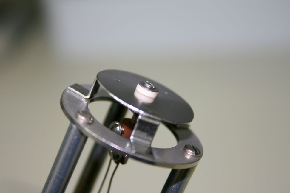
9103 float test box

9103 float test box

One end of the resistor is connected to the INPUT on the 9103 and the other end of the resistor is connected to the battery. The battery is referenced to the HV input ground on the 9103.

Finally, I connected a high voltage power supply to the ground reference via a 1 Meg ohm current limit resistor as show in the schematic below.  The current limit resistor helps to reduce noise and current surges from the high voltage supply.

Current limit resistor.jpg

After connecting the INPUT and HV leads to the 9103, I am ready to measure current. It is important to note that the 9103 Input should be set to Normal and not Grounded. (The “Grounded” Input is used to short the specimen stage to ground when not measuring current. This is useful when measuring electron or ion currents in vacuum, but when floating the 9103 you do not want to short out the input or you may damage the 9103 or your high voltage supply.)

normal not grounded

We can now measure current and can see that we are getting 913.2 nA of current.

Using the Data recorder we can monitor the current vs. time to see a graphical representation of the current.

The signal ground reference on the 9103 is tied to the high voltage supply.  As I increase the high voltage supply from 0 to 1500V DC in increments of 500V (a limitation of the high voltage supply I am using) you can see some small instabilities in the data.  This is normal; there is some capacitive coupling as the ground reference voltage is changed.  It looks like a lot of noise but in fact is only about 20 pA.

9103 graph spikes when increasing voltage

1500V DC voltage source

If you look at the data referenced to zero you can see that the instabilities are very minor and also that the output is very stable once the high voltage supply stabilizes.  If you were to measure the voltage on the 9103 HV reference to earth ground you would measure 1,500V DC.  So for this example the 9103 ground is floating by 1,500V DC.

9103 graph zero base line

In this test I changed the high voltage supply from +1500V to -1500V DC with no change in my current reading which demonstrates how well isolated the 9103 input is from earth ground.

Applications for a floating input picoammeter include measuring the output of an electron multiplier directly, as well as bias experiments with electron and ion beams.  Click here for more information on our new 5kV floating 9103.

Reusing a Helicoflex gasket

Print Friendly, PDF & Email

Can you re-use a Helicoflex gasket?  The answer is yes, sometimes.

A Helicoflex gasket uses the concept of plastically deforming to seal between two flat and polished surfaces instead of the much more common knife edge seal used with copper gaskets and CF flanges.

On Physical Electronics X-ray Photoelectron spectrometers Helicoflex gaskets are used on the monochromator, the SCA (spherical capacitive analyzer) and the LS specimen stage.

Here is a link to information on how a Helicoflex gasket works –  http://technetics.com/products/sealing-solutions/metal-seals/helicoflex-delta/

First of all, Helicoflex gaskets are designed to be used only once.   However,  since these gaskets are expensive it may be worth trying to reuse it as long as you have a new gasket on hand in case the trick I will show  you in this blog post does not work.  My success rate with this trick is about 50%.  RBD Instruments provides most of the Helicoflex gaskets used on PHI XPS systems.

For this example, I will attempt to make it possible to reuse a monochromator gasket as shown in the picture below.

monochromator_gasket

mono-chromator gasket

Note that once compressed, the center surface of the gasket is flattened out.

better_view_of_flat_area

Step one is to uncompress the gasket.   To do that, find a spot on the outside edge of the gasket where you can insert a small screw driver and gently spread open the two lips of the gasket enough to get a large flat head screwdriver inside.

insert_small_screwdriver

Then, carefully work the large flat head screw driver around the perimeter of the gasket until the entire gasket is un-compressed.  Try not to deform the edges of the slit.

insert_large_screwdriver

During this process the gasket will become deformed.  Use a round surface such as a Philips screwdriver to smooth out the bumps without re-compressing the gasket.

smooth_out

Next, using a very fine emery cloth (I used some 30uM 3M sand paper) smooth out the edges of the flat surface on the gasket.  You just want to break the edges, not make it round.

break_edge_on_flat

Clean the gasket with isopropanol or methanol to remove the small particles.

clean_with_IPA

Finally, use a small amount of Apiezon L or other HV or UHV vacuum grease to the surface of the gasket (on the flat area).   You want to use a very small amount and spread it out evenly.  The vacuum grease will help to fill in any small scratches.   Wipe off the inside and outside of the gasket.   You only want a small amount on the flat area.

small_amount_of_vacuum_grease

You are now ready to install the gasket.   Good luck!

The gasket that I used in this blog post did seal fine, so I got lucky.  🙂

Homemade Titanium Sublimation Pump

Print Friendly, PDF & Email

In this post I show how we made a small homemade titanium sublimation pump for an 8” Kimball Physics spherical octagon UHV vacuum chamber.

Our little chamber has a 60 l/s ion pump, but even with baking (both IR and UVC), we were able to get only into the low 10-8 to high 10-9 Torr range.  However, using the little titanium sublimation pump, which we “Frankensteined” together using parts we had readily available, allowed us to get in the low 10-9 to high 10-10 Torr range, a factor of ten improvement.

A titanium sublimation pump works by heating a titanium filament wire to about 1300 degrees C. That is hot enough to create titanium gas molecules (sublimate) but not so hot that the filament wire melts.  The sublimated titanium deposits on the wall of the chamber (or preferably on a shield wall) and forms a thin film. This layer of titanium is very reactive and will bond with other molecules in the vacuum chamber such as CO and O2. Disassociated hydrogen and water vapor also diffuse into the titanium layer.

The reactivity of the titanium film is increased with lower temperatures, but most titanium sublimation pumps are operated at room temperature. Over time, the titanium film will become coated and need to be replenished. All commercial titanium sublimation pumps have 3 to 4 filaments so that when one filament burns out you can switch to another. Those filaments are also relatively thick in diameter at 12 gauge (.080”) and need about 50 amps of current to operate.

For our homemade titanium sublimation pump, we used 24 gauge (.020”) so that we could operate at a much lower current of 4 amps.  We also only have one filament.

Before I show how we made our homemade titanium sublimation pump, here are links to some videos on how TSPs work:

https://www.youtube.com/watch?v=j5Y7m2ZJfgg

https://www.youtube.com/watch?v=9vJedaxRsxI

The first thing that we needed was a 2-pin electrical feedthrough on a 2.75” CF flange.  For that we used a Getter pump flange from a PHI 04-303 ion gun as shown below.

filament_wire_connections

filament_wire_connections

We then needed to somehow support and electrically isolate the TSP filament wire. To do that we used a coupler and some little shoulder washers.

Ceramic_support

Ceramic_support

The top part of the getter pump assembly is conveniently designed to allow gas molecules to pass through but also block direct deposition of titanium into the vacuum chamber.

blocks_direct_deposition

Next we added a few turns into the titanium wire so that it would have a little bit of a spring to it. Then we connected the wire to the flange and support assembly. We have only one filament and so by effectively doubling the length of the wire we could also double the amount of titanium that we would be sublimating.

filament_wire

filament_wire

For a chamber wall we used a 2.75” nipple that has a tube ID of 1.6” and a length of 4”.  The larger the surface area the better, but for the size chamber that we have, we are limited to a small 2.75” nipple. We mounted this nipple on our chamber horizontally so that any flakes that form will not get into the chamber or ion pump.

2.75_inch_CF_nipple

2.75_inch_CF_nipple

For a power supply, we used a 30 volt 5 amp Lavolta.

30V_5amp_power_supply

30V_5amp_power_supply

After installing our homemade titanium sublimation pump into the chamber we pumped down and were ready to operate the TSP.

To operate our titanium sublimation pump, we slowly increased the power supply current while observing the color of the light coming off the TSP filament and also monitoring the chamber pressure.  The filament needs to be orange for the titanium to sublimate. Too hot and the lifetime of the filament will be reduced. Too low and the pumping effect is reduced. By experimenting we determined that about 3.8 amps DC was the correct amount of current.  Once that was determined, we could just periodically turn the TSP on for about 2 minutes at a time.  We did that 3 times over a 6-hour period and then let the chamber pump overnight. The next morning we were in the high 10-10 Torr range.  Success!

tsp_filament_in_operation

tsp_filament_in_operation

Conclusions:

  1. It is possible to make a small titanium sublimation pump using off-the-shelf components that will operate with less than 5 amps of DC current.
  2. Adding a titanium sublimation pump to a small chamber can help to get from HV to UHV.