A blog on the repair, operation and calibration of surface analysis systems and components including electron spectrometers, sputter ion guns and vacuum related hardware. Click on the Index tab below to see a list of all posts. Visit our website at http://www.rbdinstruments.com
The latest software releases of Actuel for the 9103 Picoammeter and CMapp for the microCMA now support the ability to automatically read target current when acquiring data.
To use this feature, you must (of course) have a 9103 Picoammeter running RBD’s Actuel software.
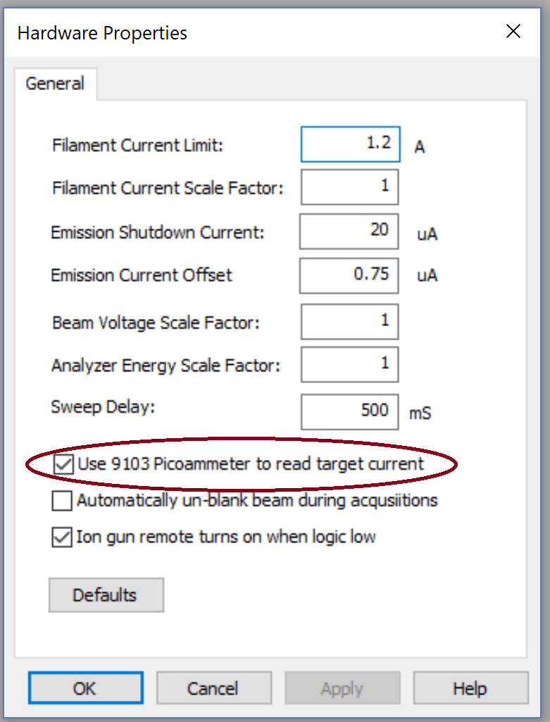
Run CMapp for the microCMA, select Hardware Properties from the System menu, and check the option “Use 9103 Picoammeter to read target current.” You only have to do this once.
Turn on the 9103 Picoammeter, run Actuel, and measure your target current as usual. Leave Actuel open. It doesn’t matter whether the 9103 is sampling, but keep in mind that your current settings (sample rate, etc.), will be used.
Now, whenever you take an acquisition (except for an alignment), the target current will be measured at the beginning of the acquisition and displayed with the other electron gun settings when the acquisition is complete.
If you don’t have a 9103, you can still manually enter a value for the target current in the acquisition dialog.
Download the latest release of Actuel for the 9103 Picoammeter here.
Download the latest release of CMapp for the microCMA here.
The heat exchanger cooling fan used on the Physical electronics 16-025 and 16-050 heat exchangers which are used to cool the x-ray sources on an XPS system can run slowly as the fan motor ages once the bearing lubricant begins to dry up. The result of a slow fan is that the anode will run warmer than normal and possibly melt. At a minimum reduced cooling will shorten the anode lifetime. The 16-020 heat exchanger has a fan that is attached to the pump motor, so it will not have this problem unless the pump motor fails.
The symptom for a slow heat exchanger fan is that with the source at full power after 20 minutes of operation the water lines to the x-ray source will be very warm or even hot rather than slightly warm.
To test the fan you can feel how much air is coming out the back side of the radiator when the 16-025 or 16-050 heat exchanger is on. The radiator will slow down the airflow, but it should still be a reasonable amount of air that escapes out the back side of the radiator. If the fan looks like it is spinning slowly and there is minimal airflow then the fan should be replaced.
If you want to test the actual RPMs of the fan you can use a non-contact laser tachometer (available for as little as $15.00). Or you can use an audio method as shown in this video on YouTube that uses Audacity:
If you determine that the fan should be replaced (or if you want to as a preventive measure if your heat exchanger is 20 years old), here is the model number information –
It is held in place with some radiator mounting rods that are available at most auto parts stores. Look for Hayden Nylon mounting rods with vibration pads.
Nylon mounting rods
In addition to the cooling fan, if the pressure indicator on your 16-050 heat exchanger bounces during operation you should consider replacing the water pump as well. RBD Instruments provides the water pumps. The 16-020 and most 16-025 heat exchangers do not have a pressure gauge.
And of course, make sure that the radiator is free from dust as being covered with dust will also reduce the cooling efficiency of the 16-020, 16-025 or 16-050 heat exchangers. Refer to the RBD TechSpot post Heat Exchanger Preventive Maintenance for more information on dust and the radiator.
Heat exchanger preventive maintenance will prolong the anode lifetime on your 10-610 mono chromator anode and prevent a costly and time consuming anode meltdown.
This post will explain the basic concept of how an electron multiplier works.
Electron multipliers are used in surface analysis instruments to boost the detected signal to a level where it can be amplified and processed into data. For Auger Electron spectrometers and X-ray photo electron analyzers the detected signal are electrons. Secondary ion spectrometers detect ions.
In the 1960s electron multipliers were made out of a series of Oxygen treated copper beryllium (CuBe) plates. Copper with 3 to 4% beryllium that is heat treated with oxygen has a secondary electron yield of approximately 3 (varies slightly for kinetic energies between 100 up to 1500V)
The drawing below shows the basic concept. One electron impacts the first plate and then a few more secondary electrons are generated. A positive voltage is applied across the multiplier array which is divided by a series of vacuum compatible resistors. Each plate is progressively more positive and so emitted electrons are attracted to the next plate. The resulting avalanche of electrons is attracted to the final collector plate where the signal is decoupled from the electron multiplier. The total number of plates determines the gain of the multiplier. Most of the CuBe electron multipliers used on Auger spectrometers had a gain of 2 X 10E6
When X-ray Electron spectrometers were first developed electron multipliers with higher gains were required in order to achieve better signal to noise. During that time continuous dynode electron multipliers (Channeltrons) were developed. Instead of a series of discrete plates, a Channeltron electron multiplier uses a high resistance semiconductor material that also has high secondary electron emissivity. Gains of a Channeltron are typically 2 X 10E7 to 2 X 10E8. The drawing below shows the gain concept. Many Channeltrons today are spiral instead of horn shaped to provide an even higher gain.
A third type of electron multiplier, the Micro Channel plate, was developed in order to obtain a larger detector surface area in conjunction with multi-channel detectors. Channel plates are essentially a lot of tiny Channeltron multipliers in parallel. Two plates are stacked on top of each other to increase the gain. The drawing below shows the gain concept. Channel plate electron multipliers are commonly used on X-ray Photo electron spectrometers.
Electron multipliers typically last for several years with normal usage. With just occasional use they can last for decades. Eventually the high secondary electron emissivity materials in the multiplier are depleted or the multiplier becomes contaminated and then the signal to noise degrades at which time the multiplier needs to be replaced.
Some additional reference links are listed below. Most of these refer to ions and mass spectroscopy but it is the same principle for electron based detectors used in Auger Electron and X-ray photo electron spectrometers.
For assistance with installing electron multipliers or channel plates in older Physical Electronics XPS and AES surface analysis instruments contact RBD Instruments, Inc.