This is the procedure that I use to ensure proper outgassing and conditioning of the PHI 04-500 and 04-548 15kV Dual Anode X-ray source after installation or bake-out. It is a slight variation from the procedure in the 32-095 out-gas activate procedure.
–
Initial Installation
After installing the source, the system must be pumped down and baked out. If you are unable to bake-out the system, you should at a minimum wrap some heat tape around the flange on the source and heat it to 150 degrees C for a period of 8 to 12 hours.
After the bakeout is complete, reconnect the water lines and check for leaks by turning the x-ray source control on for 15 minutes. Sometimes there are small leaks that form a drop or two after 5 minutes. If there are no leaks after 15 minutes you can shut off the x-ray source control and connect the high voltage lead, the Teflon shield and the second cover.
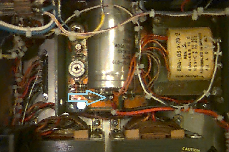
Note: Make sure that the high voltage wire is tight and that the water flow is correct. See the info at the end of this procedure for more details.
Outgas the filaments
- Turn on the 32-095/096 x-ray source control and press the Outgas/Activate button. Select both anodes and slowly ramp up each filament to 2 amps. Now, using the ion gauge as a guide, increase the filament current in ½ amp increments until you see some out gassing (usually around 3 amps).
- Over the next hour, ramp the filament current up to 4.5 amps on both filaments. Allow the source to sit at 4.5 amps for a minimum of 4 hours, overnight is better.
- After the filaments have operated at 4.5 amps for at least 4 hours, ramp them up to 5.0 amps for 30 minutes.
- Press the Outgas/Activate button to turn the filaments OFF and let them cool for 15 minutes.
- Proceed to high voltage conditioning.
High Voltage Conditioning
- Make sure that the filaments are OFF. Turn the high voltage rheostat on the high voltage control fully CCW and then press the red High Voltage button on the X-ray source control.
- Slowly turn the high voltage rheostat CW and bring the high voltage up to 5 kV. Observe the ion gauge for signs of out gassing and slowly bring the high voltage up to 8kV. The red light on the x-ray source control should stop flashing.
- Over the next hour or so, slowly bring the high voltage up to 16.5kV. Observe the ion gauge for signs of out gassing. If you see the pressure rise, back off on the high voltage a little bit and wait a few minutes. What works best is to bump up the high voltage in 500 volt increments and then to let if sit there while you go do something else. Periodically come back and bump it up another 500 volts. You can probably go up to 10kV fairly quickly, but after that you should go more slowly. The higher the kV, the more slowly you should go. Think of a rubber band that is being stretched. The further you pull it, the more likely it will snap.
- Note: The vacuum should be in the low 10-9 range when conditioning the high voltage. When the source outgases and the vacuum comes up into the mid 10-8 range, you should wait for the vacuum to go back into the 10-9 range. If the vacuum gets into the high 10-8 range the chances for an arc are good. It is best to bring it up slowly and not get any arcs as opposed to trying to force the outgas process. This takes time, be patient!
- Once you have the high voltage up to 16.5kV, leave it sit there for 30 minutes.
- Proceed to final conditioning.
Final Conditioning
- Turn on the high voltage and set it to 10kV.
- Power both filaments and bring up the power to 50 watts on both the Al and Mg anodes.
- Observe the ion gauge for signs of out gassing and let the source sit there until the vacuum returns to the low to mid 10-9 range.
- Increase the power to 100 watts per anode and increases the high voltage to 11kV.
- Slowly step the power up in 50 watt increments and the high voltage in 500 volts increments until you are at 250 watts per anode @ 15kV. This can take several hours.
- Leave the source sit there for an hour or more, until the vacuum returns to the low to mid 10-9 range.
- Decrease one anode to zero power and increase the other anode to 300 watts @ 15kV. Observe the ion gauge for signs of out gassing. If necessary, wait for the vacuum to return to the low to mid 10-9 range.
- Set that anode power to zero and bring the other anode up to 300 watts @ 15kV and observe the ion gauge.
- Once both anodes can run at 300 watts @ 15kV and the vacuum stays in the low to mid 10-9 range, then the source is fully out gassed and can be operated normally.
- If you wish to go to 400 watts you will need to run it up slowly from 300 to 400 watts the first time and let it sit there for a while.
Revised outgas procedure for PHI dual anode x-ray sources and single anode mono sources.
Outgassing the filaments and conditioning the anode are essential steps needed to remove adsorbed gases from the filament area of any PHI x-ray source.
Recently I have seen a couple of instances where a 10-610 monochromator source was not properly outgassed and the result was a contaminated anode and very low counts. So degassing the anode is essential for proper operation.
To prevent anode contamination, the anode needs to be degassed per the PHI manual. However I have found that by changing the order of the outgas procedure steps that the amount of time it takes to outgas the source to full power can be significantly reduced.
The manual states that the outgas procedure sequence is as follows:
- Outgas the filaments
- Condition the high voltage
- Degas the anode
But from a practical standpoint it makes more sense to degas the anode before conditioning the high voltage. The reason is that a degassed anode is less likely to arc.
So the faster way to outgas an X-ray soure is:
- Outgas the filaments
- Degas the anode
- Condition the high voltage
Step 1. Outgas the filaments.
You need to outgas the filaments after new filaments have been installed or anytime the system has been brought up to air and baked out. For this procedure it is assumed that the system has been baked out. (The only bake out exception is if you have just replaced the 04-303 ion gun ionizer and backfilled the chamber with dry nitrogen).
- Turn on the 32-095/096 power.
- On the 32-095/6, press the Blue Out/Act outgas activate button.
- Select both filaments
- Select the Mg filament (or filament 1)
- Slowly increase the amps to 3.5
- Select the Al filament (or filament 2)
- Slowly increase the amps to 3.5
- Let the filaments sit there for a few minutes and then slowly increase each filament to 4.5 amps.
- Let the filaments sit at 4.5 amps for a minimum of 4 hours (overnight is best).
- After outgassing for at least 4 hours set the filament current to zero on both filaments and turn off the Out/Act outgas button by pressing it one more time.
Step 2 Degas the Anode
- Set the beam voltage to 500V and turn it on.
- On the 32-095/6, press the Blue Out/Act outgas activate button
- Select the Mg filament (or filament 1)
- Slowly increase the amps to 3.5 and then monitor the anode current (emission current) meter.
- VERY SLOWY increase the filament current until you get 1mA of emission current. Do not exceed 5 amps of filament current. Do not exceed 2mA of emission current.
- Monitor the ion gauge vacuum reading and wait until the outgassing comes back down then slowly increase the beam voltage to 1 kV. If necessary reduce the filament current to keep the emission below 2mA.
- In steps of 1kV bring the high voltage up to 10kV while adjusting the filament current as needed to keep the emission current below 2mA. Do this over a period of 10 minutes to several hours, depending on how much the anode outgasses. For best results keep the vacuum in the chamber in the low 10-9 Torr range. The higher the pressure from outgassing, the more likely an arc will occur.
- Once the anode has been outgassed to 10kV, turn the filament current to zero and set the high voltage to zero. Then switch to the other filament and repeat the procedure.
Step 3 Condition the high voltage
- Make sure that the Out/Act button is OFF and that the filament current is set to zero on both filaments.
- SLOWLY bring the high voltage up to 10kV while monitoring the vacuum chamber ion gauge.
- Step the high voltage up increments of 500V until you get to 16.5kV. When you see some signs of outgassing (the pressure in the vacuum chamber will come up) then back down the high voltage a little bit and wait until the vacuum recovers.
- Once you are able to get to 16.5 kV with no arcing, let the anode sit there for at least 20 minutes.
The X-ray source is now ready for normal operation. For best results, start at a low power and kV such as 100 watts and 10kV. You can step up both the power and the kV over a period of a few hours based on how much outgassing you see when operating in this mode. Once you are up to full power of 300 watts and 15kv the X-ray source can be brought up to full power quickly.
PS RBD Instruments provides all of the replacement parts for the 04-500 and 04-548 15kV dual anode x-ray sources. Contact us for more information.