

When it comes to locating vacuum chamber leaks, there are a few different methods that can be used depending on the vacuum level of the leak.
I like to categorize leaks into three types- Gross leaks, mid vacuum leaks and high vacuum leaks.
Gross leaks are the type where the chamber will only pump down somewhere between atmosphere and the low 10-2 Torr range. With this type of leak the vacuum is not good enough for an ion gauge to turn on.
The first thing that you want to do with any leak is to make sure that all the flanges you worked on have been tightened correctly and appear uniform. If a flange has a wider gasket gap on one side than the other, then that flange may not be seated properly.
Next you will want to make sure that your pump (usually a turbo pump) can reach vacuum when not pumping on the vacuum chamber. Then while monitoring the vacuum on your turbo pump or rough pump with a TC gauge, squirt some isopropanol or methanol on suspected flanges while watching the vacuum gauge. Typically the vacuum will come down (pressure will go up) when the isopropanol or methanol finds its way into the leak. Then vent and replace the suspect gasket.
The other technique useful for gross leaks is to slightly pressurize the system with nitrogen and then squirt the suspected flanges with Snoop (or soapy water). For most vacuum chambers you do not want to pressurize them with more than 3 PSI. The reason that you do not over pressurize a vacuum chamber is because viewports are slightly concave and designed to hold vacuum, but not designed to hold pressure. Over pressurizing a vacuum chamber can cause the viewports to blow out – not good and also a safety hazard. When you find the leak, you will see bubbles forming.
For mid vacuum leaks, the ion gauge will function and the vacuum will be somewhere between the low 10-3 Torr and the high 10-8 Torr range. For this type of vacuum leak, monitor the ion gauge while squirting some isopropanol or methanol onto the suspected flanges. In this vacuum range when the isopropanol or methanol makes its way into the leak, the vacuum may improve or degrade, but you will see a definite change in the vacuum. Sometimes the isopropanol or methanol will plug up the leak momentarily and the vacuum will improve noticeably. You can use a heat gun to evaporate the isopropanol or methanol on the flange where you noticed the vacuum change. Then after the flange cools down, repeat the procedure to confirm the location of the leak.
For high vacuum leaks in the low 10-8 Torr to the low 10-9 Torr range, squirting the flange with isopropanol or methanol usually will not work. In those cases, you may need to use an RGA (residual gas analyzer) to find the leak. To use an RGA you would need to vent the chamber and install an RGA on one of the flanges, then pump back down and possibly even bake the chamber out depending on the level of the leak. For example, if the leak is in the low 10-9 Torr then you will probably need to bake out the chamber in order to get down that low.
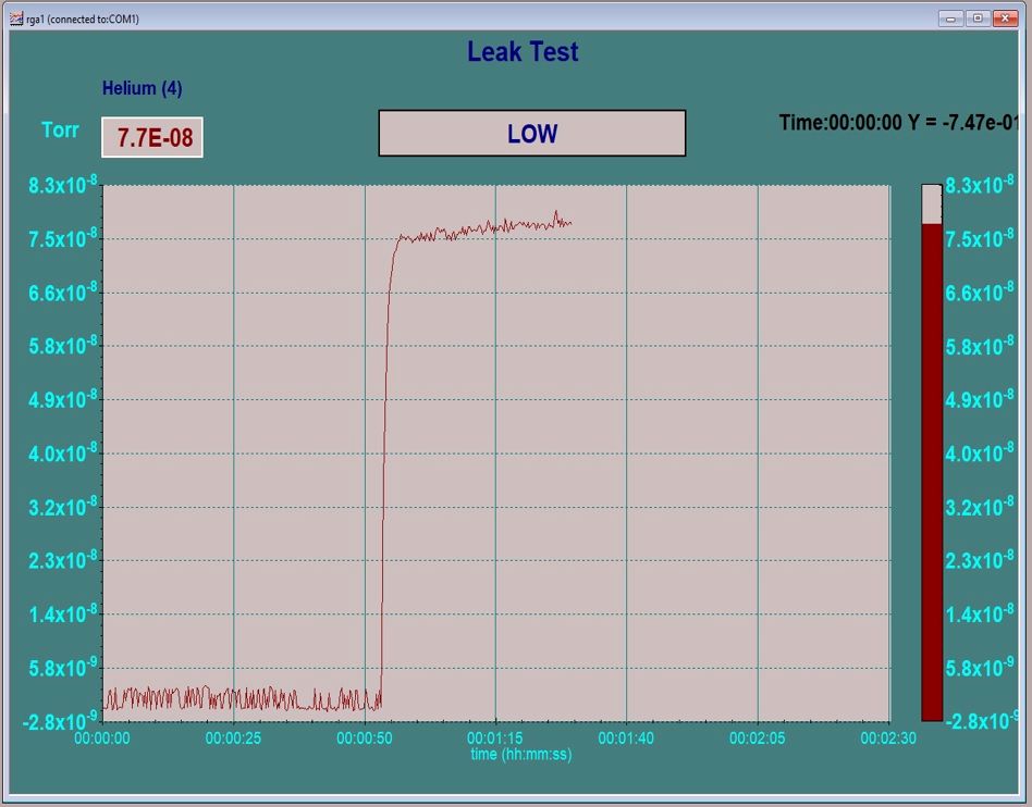
Once you are back to your base vacuum you would set up the RGA in the leak check mode or just scan over the 4 AMU helium peak. Then using helium that is connected through a regulator to a small tube, bleed a small amount of helium over the suspected flanges and feedthroughs while monitoring the helium peak on the RGA. Helium is a very small molecule and so it will pass into the leak and then be detected by the RGA. For best results I have found that you need to close off your pumps (or turn off your ion pump) while leak checking with helium. Just keep an eye on your vacuum and make sure that you pump out the chamber periodically to keep the vacuum at least in the 10-6 Torr or better. When you find the leak with helium you will see an immediate and dramatic change in the RGA scan (as shown below). It will be easy to confirm the location of the leak by pumping out the helium and then repeating the experiment.
For large industrial vacuum chambers portable leak checkers are available so that the chamber does not need to be vented to install the RGA.
What happens if you can’t find a leak? In the case of high vacuum leaks if you can’t find a leak, there may not be a leak. Sometimes what appears to be a leak is really just a whole lot of water vapor, a virtual leak or possibly hydrocarbon contamination. In these cases, a very long bake out should solve the problem. Long as in 24 or 36 hours at 150 to 200 degrees Celsius.
RGAs start at about $3,500.00 and go up from there depending on Mass range, multiplier and energy filter options. Here are some links to RGA companies –
And some technical notes:
Once you do find the leak you may need to remove water vapor from the chamber in order to obtain a better base vacuum. A number of water vapor desorption options are available from RBD Instruments at this link – Water Vapor Desorption


