This post is a compilation of some calibration tech tips that I have written over the years. The procedures listed below explain how to calibrate the following systems and units:
5600 and 5400 XPS systems, Double pass CMA XPS analyzers
Scanning Auger system, Auger analyzers
WARNING: Some of these procedures involve making adjustments in power supplies that have high voltage present. Always refer high voltage adjustments to personnel who have been properly trained in high voltage safety.
5600 and 5400 XPS systems pass energy and linearity procedure:
First, check the pass energy tracking:
Load a sample that has one side clean gold foil and the other side clean copper foil. Sputter the sample until there is no oxygen or carbon present.
Acquire a survey on clean gold from 90 to 80 eV; with low pass energy (5.85 for a 5600 or 8.95 for a 5400) at .025 eV per step.
Acquire another survey over the same range using higher pass energy (23.5 for a 5600 or 35.75 for a 5400) at .050 eV per step.
The 84.0 gold peaks should be in the same position. If not, adjust the pass energy tracking potentiometer and then reacquire the surveys. After a few iterations you should be able to get the peaks in both surveys to line up. It is not important where the energies are at this point, only that they are in the exact same position.
On 5600 systems the pass energy tracking potentiometer is located in the filter box that is connected under the SCA. CAUTION – The filter box has high voltage present. Refer adjustment to qualified personnel.
On 5400 systems adjust R36A on the pass energy board in the 80-360 SCA control in the card rack. This potentiometer is accessible from the front of the card rack without extending the pass energy card.
For older ESCA systems that use the 20-805, adjust P1 in the 20-805 – Caution, high voltage is present inside the 20-805! Refer adjustment to qualified personnel.
If you have a 20-810 digital analyzer control, adjust R81B4 on the pass energy card
Adjust the pass energy tracking potentiometer as needed to get the peaks lined up at both pass energies. The pass energy potentiometer will have a greater effect on the higher pass energy peak location.
After the pass energy tracking is correct- Use a low pass energy and acquire a multiplex on the Au 84.0 4f7 and the Cu 932.67 2p3 peaks.
Check the location of the Au 84.0 4f7 and Cu 932.67 2p3 peaks. The span between the peaks should be 848.67ev. If not, adjust the scale factor in the XPS Hardware Properties dialog box slightly, and re-acquire the multiplex. The scale factor has 4 decimal point resolution.
Adjust the scale factor as necessary to get the correct span between the Au 84.0 4f7 and 932.67 Cu peaks. This may take several iterations. The scale factor has a greater effect on the Au 84.0 4f7 peak than the Cu 932.67 2p3 peak.
If you are still running with the original PHI software you will need to extend the retard board in the 80-360 or 80-365/6 control that is located in the card rack. Caution, high voltage is present on the Retard board! Refer adjustment to qualified personnel.
Adjust the Work Function in the XPS Hardware Properties dialog box so that both peaks are in the correct locations. The work function is a linear offset that affects the high and low energy peaks equally. Make a note of the scale factor for future reference.

xps-copper-gold-peaks
AES energy calibration when using a 20-805 Analyzer Control
This procedure will calibrate the AES peak energies and 2 kV elastic peak crossover.
Tools needed: Insulated adjustment screwdriver (pot tweaker), Copper foil or gasket material.
Procedure:
- Read this entire procedure before starting the calibration.
- Load a sample of copper foil into the system and set the beam voltage on the 11-010 electron gun control to 2kV.
- Position the sample to the focal point of the analyzer using the AES Align routine. At this point it does not need to be exactly at 2kV, just make sure that the peak is maximized.
- Sputter the sample clean. Note: If you do not have a sputter ion gun on your system, then scrape the sample with a razor blade or exacto knife before you load it into the system to remove the surface carbon and oxygen.
- After the sample is clean, re-acquire the elastic peak and re-check that the peak is at maximum counts and beast shape. Do not worry if it is not at 2kV as that will be adjusted later.
- From this point on, DO NOT MOVE THE SAMPLE!
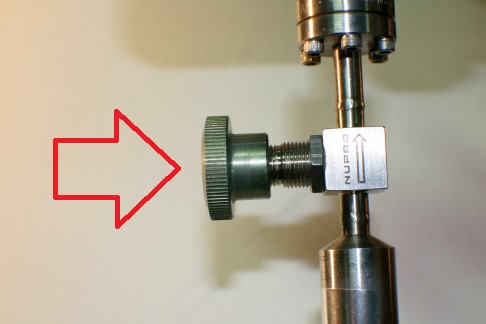
- Acquire an alignment from 900 to 960 eV and differentiate the data. The peak should be at 920 differentiated. If not, adjust the scale factor in the AugerScan Hardware Configuration menu a little bit and re-acquire the alignment and check the position. After calibrating the copper peak position, reacquire an elastic peak alignment but do not move the sample. If the n/e peak is not at 2000eV, then adjust P1 in the 11-010 control.**

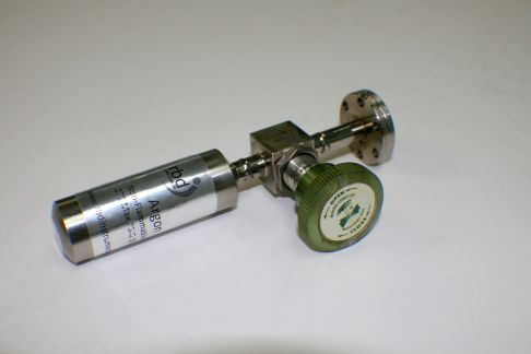
2kv-calibration-potentiometer-11010
AES energy calibration for 11-500A
Procedure:
1. Load a sample of pure copper.
2. If you are using AugerMap software, set the magnification to 10,000X and use the Area Scan mode to minimize sample topography effect on the Auger signal. Or set 20-070A to Spot Mode.
3. Perform an elastic peak alignment and adjust the Z axis sample position to obtain maximum counts and best peak shape.
4. Sputter the sample clean until no carbon or oxygen is present.
5. Re-acquire the elastic peak to ensure that the sample is at the optimum position: highest counts and best peak shape. When the elastic peak is differentiated, the positive and negative excursions should be equal and symmetrical.
6. From this point on, do not move the sample!
7. With the beam voltage at 2kV, acquire a survey from 30eV to 1030eV, using .5eV/step, 50 ms/point.
8. Differentiate the survey and check the peak positions against the correct values as listed in the PHI handbook or other reference. A typical value is 920eV for the high energy peak and 60eV for the low energy peak on copper.
9. Note: If using AugerScan software, you can simply adjust the scale factor in the AES Hardware Properties dialog box rather than adjusting the 11-500A. If necessary, adjust P3 on the 682 board for proper peak position on the high energy peak. You can acquire an alignment with a range of 900 to 940, .5eV/step, 15ms/point and do the adjustment in real time. For copper, set the n/e peak to approximately 917eV. When differentiated, the high energy Cu peak should be 920eV.
10. Acquire another survey and check that the differentiated peak positions are correct. Document the results for future reference and file it in the system calibration log.
11. Acquire another elastic peak, but do not move the sample!
12. If the elastic peak is not centered at 2kV, then adjust P9 on the 664 board in the 18-080 electron gun control until the peak is centered at 2kV. (Or P1 in the 11-010 control**)
From this point on, every-time you set the elastic peak, the sample will be at the focal point of the analyzer

Auger energy calibration on 600 and 660 scanning Auger systems
This procedure requires sliding the 20-610 high voltage supply out and removing the cover to gain access to the beam voltage offset potentiometer, R108. Turn off the 20-610 when sliding it in out or in, and when removing or installing the cover.
Procedure:
1. Load a sample of pure copper.
2. If you are using AugerMap software, set the magnification to 10,000X and use the Area Scan mode to minimize sample topography effect on the Auger signal.
3. Perform an elastic peak alignment and adjust the Z axis sample position to obtain maximum counts and best peak shape.
4. Sputter the sample clean until no carbon or oxygen is present.
5. Re-acquire the elastic peak to ensure that the sample is at the optimum position: highest counts and best peak shape. When the elastic peak is differentiated, the positive and negative excursions should be equal and symmetrical.
6. From this point on, do not move the sample!
7. With the beam voltage at 3kV, acquire a survey from 30eV to 1030eV, using .5eV/step, 50 ms/point.
8. Differentiate the survey and check the peak positions against the correct values as listed in the PHI handbook or other reference. A typical value is 920eV for the high energy peak and 60eV for the low energy peak on copper.
9. Note: If using AugerScan software, you can simply adjust the scale factor in the AES Hardware Properties dialog box rather than adjusting the 32-150. If necessary, adjust R58/G3 (AES fine gain) and adjust R61/H3 (AES coarse gain) for proper peak position on the high energy peak. You can acquire an alignment with a range of 900 to 940, .5eV/step, 15ms/point and do the adjustment in real time. For copper, set the n/e peak to approximately 917eV. When differentiated, the high energy Cu peak should be 920eV.
10. Acquire another survey and check that the differentiated peak positions are correct. Document the results for future reference and file it in the system calibration log.
11. Acquire another elastic peak, but do not move the sample!
12. If the elastic peak is not centered at 3kV, then adjust R108 in the Bertan 20-610 High Voltage power supply to center the elastic peak.
Calibration is complete.
From this point on, every-time you set the elastic peak, the sample will be at the focal point of the analyzer (maximum signal and best shaped peak), and all of the Auger peaks will be in the correct positions.
**– Caution, high voltage is present! Refer adjustment to qualified personnel.