A blog on the repair, operation and calibration of surface analysis systems and components including electron spectrometers, sputter ion guns and vacuum related hardware. Click on the Index tab below to see a list of all posts. Visit our website at http://www.rbdinstruments.com
Category Archives: General Optics and Vacuum
General information on repair, maintenance, and operation of both PHI (Physical Electronics) and other manufacturers’ systems and components
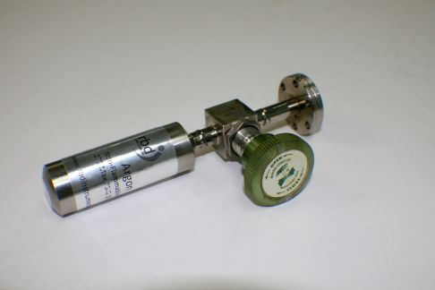
RBD Instruments provides a refill service for the Argon, Oxygen, and Xenon gas bottles that are used with the PHI 04-303 and 06-350 sputter ion guns on many x-ray photoelectron and Auger spectrometers.
argon-bottle
When you replace the argon or oxygen bottle on your PHI system, a small volume of air is introduced between the bottle and the leak valve. This air needs to be pumped out. The process for replacing the bottle and pumping out the air is different for systems with and without poppet valves. Both procedures are provided here.
Replacing Bottles on Systems without a Poppet Valve
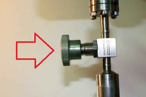
1. Close the leak valve.
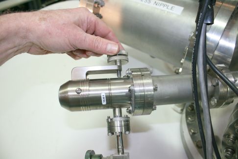
2. Keeping the valve on the new bottle closed, remove the old bottle and install the new one.
3. Turn off all filaments on the system, including the DIG.
4.Turn off the Boostivac ion pump control.
5. Open the leak valve all the way.
6. Turn on the turbo pump and pump intro.
7. After the turbo has reached full speed, open the V1 gate valve and pump out the system for about 10 minutes with the turbo pump.
8.Close the V1 gate valve.
9.Start the ion pumps.
10 Turn on the DIG.
11. Pump until the base vacuum returns to normal.
12. Close the leak valve.
13. Open the argon bottle.
Replacing Bottles on PHI systems with a Poppet Valve
1. Close the leak valve.
2. Keeping the valve on the new bottle closed
3. Remove the old bottle and install the new one.
3. Turn off all filaments on the system including the DIG.
4. Close the poppet valve.
5. Open the leak valve all the way.
6. Turn on the turbo pump and pump intro.
7. After the turbo has reached full speed, ope
n the V1 gate valve and pump out the
System for about 10 minutes with the turbo pump.
8. Close V1 gate valve.
Open the poppet valve.
10. Turn on the DIG.
Pump until the base vacuum returns to normal.
Close the leak valve.
Open the argon bottle.
Visit our website at rbdinstruments.com for more information and to request a quotation. Or call us at 541 550 5016.
The Auto Valve Control (AVC) controls all of the air valves on many PHI systems. It has built in logic that uses two thermocouple sensors and a mechanical switch to determine the status of the system.
There are four common problems with the AVC:
1. The V4 ion gun valve will not open in the automatic mode.
2. The gate valve will not close when the probe is retracted.
3. The V1 led on the remote is neither Red (closed) nor Green (open).
4. One or more of the solenoids stick, or leak.
Problems/Solutions:
1. The V4 ion gun valve will not open in the Automatic mode.
There are two thermocouple gauge tubes that sense the vacuum of the turbo(s), but only one TC gauge. TC1 is located on top of the turbo and determines whether or not the turbo pump is up to full speed. TC2 is under the tabletop and measures the vacuum in the intro chamber. If the intro pumps down to 5 bars but the V4 valve will not open, either the TC gauge is out of adjustment, or TC1 is defective.
To adjust the TC gauge:
1. Remove the cover on the AVC and slide it out enough to work is able to access inside of the unit. On some systems, such as the 600 Multiprobe, you can remove the tabletops and come from the top down. On other systems, such as 5000 series XPS systems, you will need to slide the AVC out of the rack a little bit.
2. Refer this adjustment to qualified personnel. With a DVM, measure the voltage on pins 1 and 2 of P14. This is the connector that comes from the TC gauge control output. Pump down the intro. After you have 5 bars, you should have 9 to 10 mV DC on pins 1 and 2 of P14. If not, there is a pot on the back of the TC gauge (hockey puck) that needs to be adjusted. There is a hole on the back of the AVC that might allow you to do the adjustment from the back of the AVC with a long, thin screwdriver. Usually this does not line up and you need to remove the 3 screws at the base (under side of the AVC) that hold the TC gauge to the AVC and rotate the TC gauge up to get to the pot. Adjust the pot for 9 to 10 mV. It goes from Zero mV (air) to 10 mV (vacuum). CAUTION! If you have to move the TC gauge exercise extreme caution! There is a 220-volt AC terminal strip located near the TC gauge. It is recommended that the AVC be shut down (close all valves and turn off all turbo pumps first) and un-plugged before tilting the TC gauge. Touching the metal case to the exposed 220-volt AC terminal strip will cause arcing, damage to the AVC and possible electrical shock!
AVC-control-board
NOTE:
RBD provides an upgrade to AVC units where the P14 and TG guage pots are mounted on the front panel of the AVC. We install this upgrade as part of a standard AVC repair.
3. After you have the TC gauge adjusted for 10 mV, adjust R103 (The only adjustment pot in the AVC) for 4 bars on the AVC remote. The fifth bar is timed and comes up automatically after two minutes, provided that the vacuum stays at 4 bars. Find the threshold for 4 bars, and turn it an additional 1 full turn. There is some hysteresis in the adjustment.
Calibration of the TC gauge is now complete. If the V4 valve still does not open in the automatic mode, then the Thermocouple tube TC1 located on the turbo is most likely defective or out of range. Since there is only one controller, both of the thermocouple tubes need to be matched somewhat closely in performance.
You can purchase these tubes from RBD, our part number is DST06MRE.
2. The gate valve will not close when the probe is retracted.
If the V1 gate valve does not close automatically after retracting the intro probe, most likely the intro probe switch is broken.
1. Remove the probe bnc cable from the intro (located under the intro chamber near the pumping line).
2. Short the center pin on the cable to the outer shield on the cable.
3. V1 should now close. If so, then the intro probe switch is broken and needs to be repaired/replaced.
You can operate the intro by shorting the cable to close the V1 valve until it is convenient to remove the intro from the gate valve and repair/replace the switch (make sure the turbo pump is OFF before you remove the intro). PHI’s part number for the switch is 613174. You can also usually repair or replace these with a piece of spring steel for much less than the price of a new switch.
If you have a magnetic load lock arm then sometimes the magnetic sensing switch can fail. If so, contact RBD for a replacement.
3. The V1 led on the remote is not Red (closed) or Green (open).
Sometimes when there is a power outage the AVC will not be re-set properly unless the probe is fully retracted first.
1. Make sure that all valves are closed.
2. Pull the probe all the way out.
3. Make sure that the AVC is in the Automatic (not manual) mode.
4. Turn the AVC off.
5. After one to two seconds, turn the AVC back on. Do not leave it off too long or the turbo pump will vent.
The V1 light should now be red. If not, there is a problem with the AVC. Contact RBD Instruments for assistance at (541)330-0723 or at rbdinstruments dot com
4. Any one of the valves sticks, does not open, or leaks.
After some number of years, the solenoids that drive the air-actuated valves become dried up. The result is intermittent operation. Sometimes the valves will stick open, other times closed. You can take the solenoids apart and lubricate the seals with vacuum grease. This is somewhat difficult to do and can result in the valve being totally inoperable. The best solution is to replace the defective solenoid with a new one. RBD has these parts in stock at all times.
If you have an older Balzers Pfeiffer Duo 1.5 mechanical pump that needs to be rebuilt and want to do it yourself, here is a link to a detailed procedure: