How to clean a nude ion gauge

Print Friendly, PDF & Email

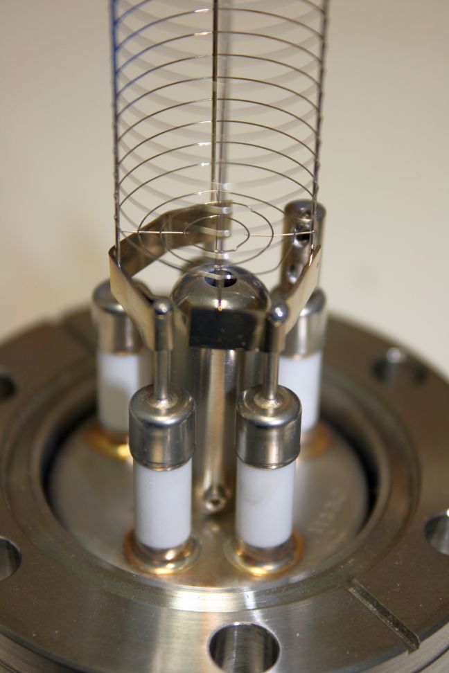
The ceramic feedthroughs on the nude ion gauges commonly used in vacuum chambers can become coated over time which results in non-accurate or unstable readings.  The following procedure can be used to clean the coating off of the ceramics.  Install a new filament assembly on the clean feedthrough flange and voila! – You have a rebuilt ion gauge.  RBD provides the filament assemblies for a wide variety of ion gauges.  If you can’t or don’t have the time to clean the feedthrough assembly on your coated ion gauge, RBD also provides complete ion gauges at great prices. The RBD Instruments ion gauge filaments and complete gauges can be found at this link – Low Cost Ion Gauge Filaments


dirty-ion-gauge-feedthrough

dirty-ion-gauge-feedthrough

cleaned-ion-gauge-feedthrough

cleaned-ion-gauge-feedthrough


Ion gauge cleaning procedure

Note: This procedure can be used to clean the tungsten and carbon coating off of the ion gauge ceramic feedthroughs. It is not intended for ion gauges that are contaminated with oil. If your ion gauge is contaminated with oil it should be replaced.

  1. Tape a used gasket to the flange. This is to ensure that the knife edge is protected (rule # 1).
  2. With the ion gauge flange pointing down, sandblast the ceramics with clean alumina. Avoid the grid.
  3. With the ion gauge flange pointing down, sandblast the ceramics and metal can with clean glass beads. Avoid the grid.
  4. With the ion gauge flange pointing down, move the sand blast nozzle as far away from the ion gauge as possible and sand blast the grid lightly with clean glass beads to remove any black contamination from the grid. You not want to get the nozzle too close to the grid as the air blast will damage the grid and or bend the collector wire.
  5. Shake off any excess blast material.
  6. Rinse off the ion gauge flange with water.
  7. If necessary, straighten any of the grid wires that may be bent out of position
  8. With the ion gauge flange facing down, place the ion gauge into a beaker filled with 5% Alconox or another lab detergent and water. Ultrasonic for 5-10 minutes. Warm water works best.
  9. Remove from beaker and rinse well with water.
  10. Place ion gauge flange face down in a beaker of DI water with no soap.
  11. Ultrasonic for 5-10 minutes
  12. Remove from water and rinse thoroughly with DI water.
  13. Dunk once into Isopropanol (to remove the water).
  14. Blow off excess Isopropanol (especially from inside the cap where the collector wire is located) and then dry in an air oven for 1 hour at up to 200C.
  15. Install new filament assembly.

Rebuild is complete!

When you install the ion gauge back into your vacuum chamber you will need to run it through one or two degas cycles.

Also check out the RBD Techspot blog post on how to install an ion gauge filament.

15-255G Filament Change Procedure

Print Friendly, PDF & Email

This post explains how to replace the C75-010 tungsten filament used in the Physical Electronics 15-255G double pass CMA.    Refer to the pictures below for more details.  RBD Instruments provides the C75-010 filaments as well as any other parts that you may need for your 15-255G analyzer.  We also offer a complete analyzer rebuild service that includes a new filament and electron multiplier.

15-255G Filament Change Procedure

 Use gloves, de-magnetize all tools and clean all tools with Isopropanol.  Set up a work area with UHV aluminum foil.  Or use regular aluminum foil and clean it with isopropanol.

Set analyzer on stand or use manuals and support analyzer on handles, facing up.

  1. Remove outer magnetic shield (3 screws)
  2. Remove inner magnetic shield (4 screws)
  3. Carefully remove conical ceramic cover.   Note that sometimes the conical ceramic will stick inside the cover. Be careful not to let it fall out if it does stick. If it falls out an breaks a replacement conical ceramic is expensive!
  4. Remove conical ceramic and carefully set it on the aluminum foil.
  5. Carefully lift inner cylinder up and off of the electron gun assembly. Note: If the inner cylinder does not move freely, use a heat gun to expand the inner cylinder so that it will slide off. Do not force it! Be careful not to damage the grids.
  6. Look at the electron gun detail to familiarize yourself with the electron gun assembly.
  7. Remove the deflection cover (3 small flat head screws)
  8. Remove the deflection support screws (4 flat head)
  9. Remove the deflection support post that is located between the two ceramic posts.
  10. Tilt the electron gun out and down so that you can access the bottom plate of the electron gun.
  11. Remove the three long screws that hold the electron gun assembly together.
  12. Remove the V1 emission screw
  13. Remove the 2 filament couplers from the filament posts. You will need a .048 4 spline wrench.
  14. Remove the 3 filament support ceramics.
  15. Remove the filament whenelt cap assembly. Note the orientation of the emission tab and filament posts as when you put the new filament in it will need to have the same orientation.
  16. Remove the 3 screws that hold the filament base on and remove the filament.
  17. Install the new filament in the same orientation as the old filament into the emission cap.
  18. Install the 3 screws and the filament base and tighten slightly.
  19. Position the filament so that it is centered in the hole and tighten the 3 screws. This is best done using a microscope. For best results the tip of the filament should be perfectly centered.
  20. Install the filament assembly on top of the 3 filament support ceramics and use the 3 long screws to hold the assembly together. The three long screws need to be tightened firmly so that they all have the same distance with respect to the base.
  21. Reconnect the V1 wire
  22. Reconnect the filament couplers.
  23. Install the deflection support post, screws and cover.
  24. Ohm out the connections to the filament and V1.
  25. Degauss the gun assembly.
  26. Install the inner cylinder over the electron gun assembly.  Line up the dead spots on the ceramic tubes.
  27. Reinstall the upper outer cylinder.
  28. Carefully install the conical ceramic. The resistor part should be 180 degrees out from the center flat ceramic. Ohm out OC (outer cylinder) to ground and make sure it has the correct resistance of 600 k ohms +/- 100 k ohms.
  29. Install the conical cover and tighten the screws firmly and evenly.
  30. Install the inner magnetic shield
  31. Degauss the analyzer.
  32. Install the outer magnetic shield.
  33. Degauss the analyzer. Installation complete.


This slideshow requires JavaScript.


Deionizer flow restrictor

Print Friendly, PDF & Email

Deionizer flow restrictor for PHI X-ray source heat exchangers

This post is a reprint of a tech tip that we published in our fall 2008 Service Detail newsletter. This exact problem came up recently and so I thought I would resurrect this tech tip for educational purposes. In the recent case we knew that the leakage current was very high and it had been several years since the deionizer cartridge was replaced. Replacing the deionizer cartridge was the logical solution. Replacing the cartridge did solve the problem for a while, but within a very short time the leakage current problem returned. Cleaning out the flow restrictor as described below solved the problem.

If you need replacement water filters or deionizer cartridges for your PHI 16-020 or 16-050 X-ray source heat exchangers that are available at this link – PHI Optics Parts

Deionizer flow restrictor inspection and cleaning procedure:

The 04-500 and 04-548 15kV dual anode x-ray sources are water cooled by a closed loop radiant heat exchanger (model 16-020, 16-050) which includes a built in water filter and deionizer cartridge. Since the anode floats at 15kV, the water must be kept in a constant state of deionization to prevent leakage current. If the leakage current is more than 2 or 3 mA at 15kV of high voltage then the leakage current will start to affect the power regulation on the 32-095 or 32-096 X-ray source control. Normal leakage current (the current that is shown on the HV supply current meter when only the high voltage and no power is applied) should be less than 2mA @ 15kV. Once you get up to 3 to 5mA it is time to replace the water filter and deionizer cartridge.  If the leakage is very high (10mA or more) then it is possible that the heat exchanger flow restrictor is plugged up.

Part of the loop in the cooling flow directs about 10% of the water through the deionizer and filter. There is a flow restrictor just in front of the input to the filter and this flow restrictor can become clogged or corroded over time, resulting in reduced flow to the deionizer cartridge and subsequent increased leakage current.

It is recommended that every time you replace the deionizer cartridge and filter (about once every 3 years is typical) that you inspect the flow restrictor and clean it out if necessary. If it is corroded you may need to drill it out with a tiny drill bit (about .030″).

The pictures below show the location of the flow restrictor and how to remove it for inspection. If it is plugged up then drill it out with a small drill bit and clean it before reinstalling it into the flow restrictor connector

This slideshow requires JavaScript.